Automatic Cooling Fan Controller for Audio Amplifiers

In the world of audio amplifiers, maintaining optimal temperatures is crucial to ensure peak performance and prevent overheating. We're going to show you how to build a simple yet effective Automatic Cooling Fan Controller for your audio amplifier. We'll be using the ATmega328 microcontroller, which can be programmed easily with Arduino. This controller is designed to work with three cooling fans and includes a NTC temperature sensor for precise temperature monitoring. We've also added an optocoupler to keep the fan's power supply separate from the rest of the circuit. Let's dive into this exciting DIY project step by step.
Project Overview
The Amplifier Cooling Fan Controller is designed to monitor the temperature of your amplifier and adjust the fan speed accordingly. Here's an overview of the project:
- Temperature Sensing: We will use a temperature sensor (10k NTC) to measure the amplifier's temperature accurately.
- Microcontroller Control: The ATmega328 microcontroller will read the temperature data and determine the appropriate fan speed based on a predefined threshold.
- Fan Control: BD139 transistor will be used to control the fan's speed. The microcontroller will adjust the PWM signal to control the fan speed effectively.
- Preventing electrical noise: The inclusion of an optocoupler adds an extra layer of safety by isolating the fan's power supply from the rest of the circuit, preventing any potential electrical noise or interference.
What You'll Need
Before we begin, gather these items:
- ATmega328 Microcontroller
- Arduino Uno (for programming)
- 10K NTC Thermistor
- 12V DC Fans
- PC817 Optocoupler
- BD139 Transistor
- Capacitors
- Resistors
- Diodes
- 16mhz crystal oscillator
- Breadboard or a PCB Board
The components values are listed below.
Step-by-Step Instructions
Step 1: Circuit Design
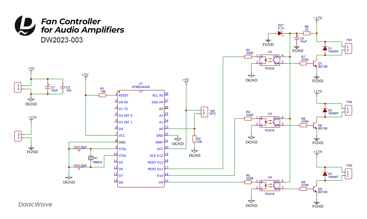
Construct the circuit using the provided design on either a breadboard or a PCB. Next, gather all the components and assemble them onto the PCB board. Refer to the circuit diagram provided below.


Part list
| U1 | ATmega328 |
| U2, U3, U4 | PC817 Optocoupler |
| Q1, Q2, Q3 | BD139 Transistor |
| NTC | 10K |
| C1, C5 | 10uF |
| C2 | 104 |
| C3, C4 | 22pF |
| R1, R2 | 10K |
| R3 - R5 | 330R |
| R7 - R9 | 270R |
| X1 | 16MHZ |
| D1 - D3 | 1N4007 |
| ZD1 | 5.1V |
Step 2: Programming the ATmega328
You'll need to program the ATmega328 microcontroller using an Arduino board. Write code that reads temperature data from the sensor and adjusts the fan speed accordingly. Here's a simple code for this.
// Cooling Fan Controller
// by DaacWave <https://www.daacwaves.com/>

const int tempSensor = A0;    //Temperature sensor input
const int exosFan = 11;       //Fan1 output
const int coolingFan1 = 10;   //Fan2 output
const int coolingFan2 = 9;    //Fan3 output

int sensorValue = 0;
int outputValue = 0;

void setup() {
  pinMode(exosFan, OUTPUT);
  pinMode(coolingFan1, OUTPUT);
  pinMode(coolingFan2, OUTPUT);

  analogWrite(exosFan, 0);
  analogWrite(coolingFan1, 0);
  analogWrite(coolingFan2, 0);
}

void loop() {
  sensorValue = analogRead(tempSensor);
  outputValue = map(sensorValue, 0, 1023, 0, 255);

  if (sensorValue < 600) {

    analogWrite(coolingFan1, 0);
    analogWrite(coolingFan2, 0);
    exosFanControl();

  } else if ((sensorValue > 600) && (sensorValue < 620)) {

    analogWrite(coolingFan1, 100);
    analogWrite(coolingFan2, 0);
    exosFanControl();

  } else if ((sensorValue > 620) && (sensorValue < 640)) {

    analogWrite(coolingFan1, 180);
    analogWrite(coolingFan2, 0);
    exosFanControl();

  } else if (sensorValue > 640) {

    analogWrite(coolingFan1, outputValue);
    analogWrite(coolingFan2, outputValue);
    exosFanControl();
  }
}

void exosFanControl() {
  analogWrite(exosFan, 255);
  delay(30000);   // 30 second exosfan ON

  analogWrite(exosFan, 0);
  delay(180000);  // 3 mins exosfan OFF
}
Describing the provided code
Three fans have been incorporated into the code. The first one is an exhaust fan, which operates on a time-based schedule. It runs for 30 seconds and then turns off for 3 minutes, repeating this cycle. The other two fans are dedicated to cooling the heat sink, and their operation is dependent on the level of heat.
When the 'sensorValue' falls below 600, both cooling fans are in the off mode. When the 'sensorValue' ranges between 600 and 620, the first fan operates at a normal speed. If the 'sensorValue' ranges between 620 and 640, the speed of the first fan increases. When the 'sensorValue' exceeds 640, both fans operate at speeds determined by the level of heat.
Keep in mind that this is a simplified example, and the actual code may vary depending on your specific amplifier, cooling fan, and temperature sensor setup. You would need to adjust the code to match your hardware and temperature monitoring requirements.
Step 3: Assembling the Hardware
- Connect the microcontroller, NTC, and fans on your breadboard or PCB according to the circuit diagram.
- Ensure all connections are secure and double-check for any loose wires or shorts.
Step 4: Testing
- Power up the circuit using a 12V power supply for the Fans and 5V for the microcontroller. Don't connect the FGND and DGND together (Check the circuit diagram)
- Manually set the temperature for the NTC. You can test it with a soldering iron or other heating sourse.
- Monitor the fan's behavior as the temperature changes. Make any necessary adjustments to the temperature thresholds in the code.
Documents
Download FilesConclusion
With this easy guide, you can create your own Cooling Fan Controller for your audio amplifier. By using the ATmega328 microcontroller, Arduino, a 10K NTC temperature sensor, and an optocoupler for safety, you'll keep your amplifier cool and performing at its best.
Always be careful when working with electronics, and double-check your connections before turning on the circuit. This project not only improves your amplifier's performance but also provides a fun learning experience for electronics enthusiasts. Enjoy building!